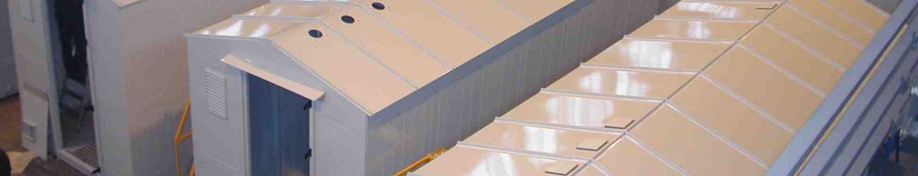
Complete transformer substations in a single casing CTS 10/0,4 kV with a transformer 25-1000 kVA
Complete transformer substations in a single casing CTS 10/0,4 kV with a transformer 25-1000 kVA are designed for receiving, converting and distributing electrical energy of three-phase alternating current of industrial frequency 50 or 60 Hz, and is used for power supply of agricultural and industrial facilities, oil and gas fields, individual settlements and residential areas, as well as infrastructure facilities of companies .
CTS are designed to operate in the following conditions:
- installation height above sea level is not more than 1000 m;
- ambient air temperature according to GOST 15150 and GOST 15543.1:
-45°C to +40°C for climatic version and location category U1;
-60°C to +40°C for climatic version and location category UHL1;
- environment – industrial atmosphere of type II according to GOST 15150 (not explosive, not containing chemically active gases and vapors in concentrations that reduce the parameters of the transformer transformer substation within unacceptable limits); ice wall thickness no more than 20 mm;
- degree of protection of the shell IP34 according to IEC 60529.
Classification of CTS:
| By type of power transformer | - oil - dry |
| According to the method of making the neutral of the transformer on the low voltage side | - with solidly grounded neutral |
| По числу применяемых силовых трансформаторов | - с одним трансформатором; - с двумя трансформатораим |
| Availability of busbar insulation in the switchgear on the LV side | - with non-insulated busbar |
| According to the design of the high-voltage input | - cable - air |
| For making conclusions on the LV side | - output up; - output down |
| Climatic design and placement category GOST 15150 | - U1; - UHL1 |
| Insulation level according IEC 60071 | - normal |
| According to the method of installing circuit breakers | - stationary; - plug-in. |
Technical data:
| Power transformer, kVA | 25 - 1000 |
| Input current transformers (transformation ratio): rated current primary, A / secondary, A | 50/5 - 1500/5 |
| Rated fuse current 6 kV, A | 8 - 160 |
| Rated fuse opening current 6 kV, kA | 20; 31,5; 40 |
| Rated fuse current 10 kV, A | 5 - 100 |
| Rated fuse opening current 10 kV, kA | 12,5; 20; 31,5 |
| Thermal resistance current on the LV side for 1 s, kA | 10; 20 |
| Electrodynamic resistance current on the LV side, kA | 25; 51 |
| Rated voltage on the HV side, kV | 6; 10 |
| Rated insulation voltage on the HV side, kV | 7,2; 12 |
| Rated voltage on the LV side, kV | 0,4 |
| Rated making current, kA | 20 |
| Electrodynamic resistance current for a duration of 1 s, kA | 51 |


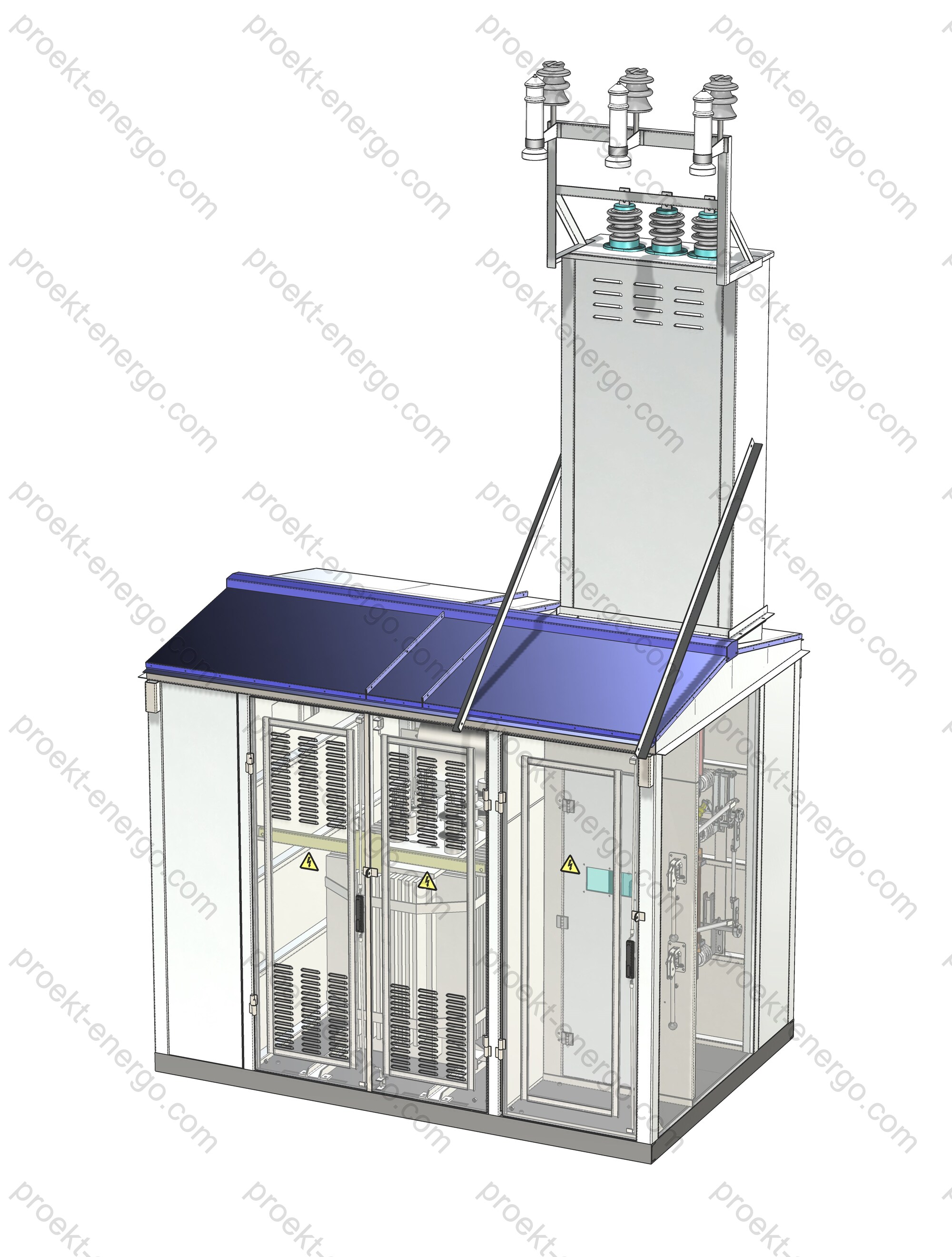
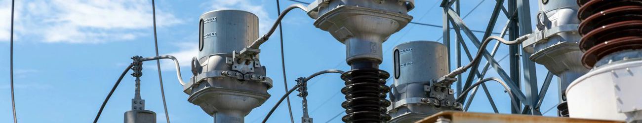
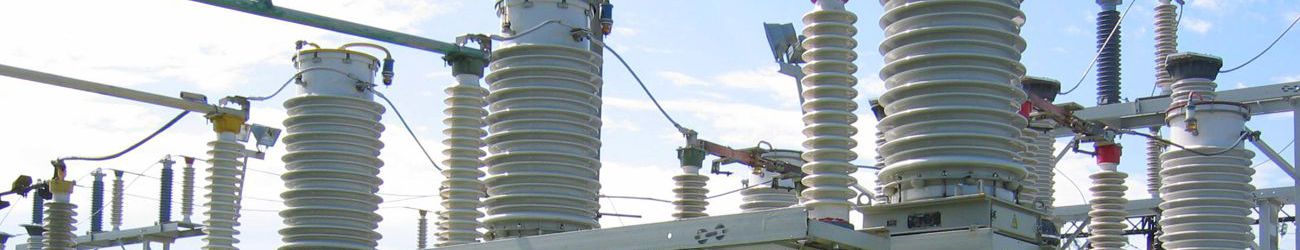
The CTS is structurally designed with high-voltage and low-voltage inputs from overhead and cable lines. To connect to overhead lines, a portal with pin and bushing insulators is installed on the roof of the substation, allowing you to safely connect an uninsulated high-voltage wire. When aerial input of outgoing LV lines is carried out, their output is carried out through the above-mentioned portal, which has the necessary design for this. A single-transformer transformer substation consists of three compartments enclosed in a single metal casing:
- power transformer (TS) compartment,
- high voltage (HV) compartment (at powers up to 630 kVA, without the use of load switches, it can be combined with the power transformer compartment),
- LV compartment with one-way service from the street,
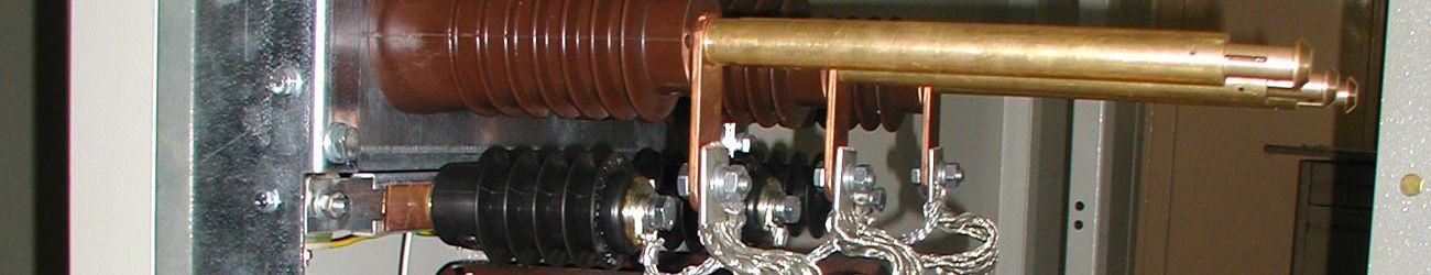
The high-voltage air input and line disconnector installation unit are located on a separate support.
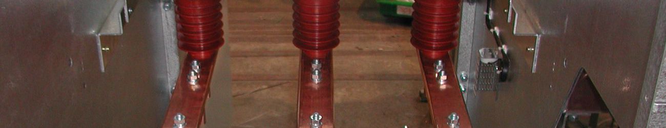
In a single-transformer package substation, the transformer compartment is equipped with double-leaf gates on both sides, designed for ease of maintenance and dismantling of the power transformer. The HV compartment has several types:
- with fuses without a disconnect device for dead-end single-transformer substations with a power of up to 630 kVA;
- with autogas load switch with grounding blades and fuses;
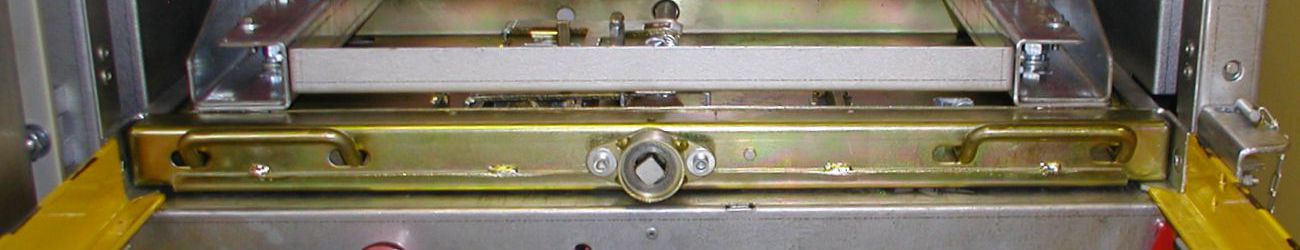
The load switches in the HV compartment are equipped with:
- a device for shutting down the device when the fuse link burns out;
- mechanisms for blocking the switching on of grounding knives under load and switching on the load when grounding knives are applied;
- interlocking with an external line disconnector.
The HV compartment has an external gate for access to the compartment to the load switch drives and an internal door (doors) blocking access to the load switch, which has an inspection window for inspecting the condition of the device. For cable entry, the floor of the compartment has a hole for cable entry and a bracket for fixing them.
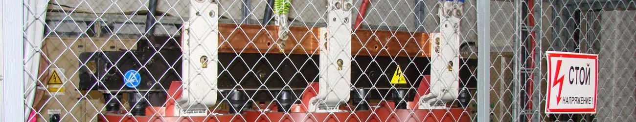
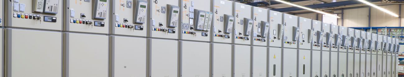
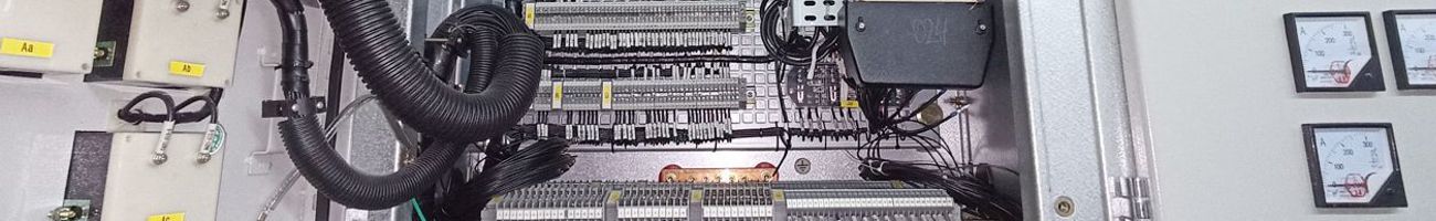
The low-voltage compartment is a compartment for access and maintenance of equipment; there are double doors, one-way service from the street. Low-voltage devices, equipment and busbars in the compartment are distributed over the area of the rear wall on supporting brackets, which when assembled form a panel with equipment. The input device of the low-voltage compartment is located centrally in the upper part of the panel, the busbars are located horizontally, and underneath them there are automatic switches of outgoing lines in a row. Relay control and protection equipment, electricity metering equipment at the input are grouped above the busbars to the right and left of the input apparatus and, depending on the design, can be placed inside wall cabinets.
We offer you documentation for the manufacture of complete transformer substations in a single casing CTS 10/0,4 kV with a transformer 25-1000 kVA:
- Preliminary technical documentation for participation in tenders for the manufacture of CTS. We will prepare for you the necessary information to assess the possibility of manufacturing products in accordance with the requirements of tender documentation and questionnaires.
- Working drawings, 3-D models, and other necessary documentation for the manufacture of CTS at your enterprise. If you do not plan to independently manufacture components and parts of the product, we will help you place their production at third-party enterprises. General assembly of the product and installation will be carried out at your enterprise.
- All documentation, if necessary, is adjusted in accordance with the requirements of the project, as well as in accordance with the technological capabilities of your enterprise.
- If equipment from another manufacturer is installed at the substation, we will prepare for you documentation for the manufacture of similar equipment in addition to the installed one
Advantages of working with us:
- You do not need to employ highly qualified engineers - You receive a set of documentation for the product being manufactured, which can be operated by a semi-skilled engineer.
- You do not need to manufacture prototypes of products - our experience allows us to successfully launch serial batches of products for production.
- Working according to our documentation - your specialists will receive advice on all the nuances of manufacturing switchgear CTS.
For additional information on CTS, please contact: This email address is being protected from spambots. You need JavaScript enabled to view it.
... and, as you know, a mistake made during the design of a product results in 10-fold costs during manufacturing, and 100-fold during its operation...